
Testing a Relay: Expert Techniques Revealed
Testing a Relay: Expert Techniques Revealed
A relay is an electromagnetic switch that controls high-current circuits using a low-current control signal. Understanding how to test a relay is essential for anyone working with automotive systems, HVAC units, industrial equipment, or home automation. Whether you’re troubleshooting a car that won’t start, a furnace that’s acting up, or electrical appliances that have stopped working, knowing the proper testing methods can save you time and money.
Relays fail for various reasons including coil burnout, contact corrosion, mechanical wear, and electrical overload. Testing helps you determine whether a relay is functioning properly before replacing expensive components or calling a professional. This comprehensive guide reveals the expert techniques used by electricians and automotive technicians to diagnose relay problems accurately.
Understanding Relay Basics
Before diving into testing methods, it’s crucial to understand what a relay does and how it works. A relay operates on a simple principle: a small electrical current flowing through a coil generates a magnetic field that pulls a mechanical switch, allowing a much larger current to flow through a separate circuit. This makes relays invaluable in automotive and home electrical systems where you need to control powerful devices with minimal power input.
Relays come in various configurations, but the most common types include single-pole single-throw (SPST), single-pole double-throw (SPDT), and double-pole double-throw (DPDT) designs. Each configuration has different terminal arrangements and functions. Understanding your specific relay type is the first step toward accurate testing. Most relays have four or five terminals: the coil terminals (typically labeled 85 and 86) and the switch contacts (labeled 30, 87, and sometimes 87a).
The coil circuit operates independently from the switch contacts circuit, which is why testing requires checking both components separately. A relay might have a working coil but failed contacts, or vice versa. This dual-circuit design is what makes proper testing methodology so important.

Tools You’ll Need
Testing a relay doesn’t require expensive equipment, but having the right tools makes the process much more efficient and accurate. Here’s what every DIYer should have in their toolkit:
- Digital Multimeter: The most essential tool for relay testing. Look for one with continuity testing capability, which produces an audible beep when circuits are complete. Brands like Fluke and Klein offer reliable models suitable for home use.
- Relay Test Box: A specialized device that simplifies relay testing by providing power and measuring functionality. While not essential, professional electricians often use these for quick diagnosis.
- Battery or Power Supply: A 12V automotive battery or adjustable power supply helps energize the relay coil during testing.
- Jumper Wires: Essential for safely connecting components and creating test circuits without permanent connections.
- Wiring Diagram: Documentation specific to your relay type showing pin configurations and proper connections. Most manufacturers provide these online.
- Safety Equipment: Insulated gloves and safety glasses protect you when working with electrical components.
Having these tools ready before you begin ensures a smooth testing process and reduces the risk of damaging the relay or injuring yourself.
Visual Inspection Methods
The first step in testing any relay is a thorough visual inspection. Many relay failures are immediately apparent once you examine the component closely. Start by removing the relay from its socket and inspecting all visible surfaces.
Check for physical damage: Look for cracks in the plastic casing, burned areas, or corrosion on the terminals. Heat damage appears as discoloration or melting of the plastic housing. If you notice a burnt smell when you remove the relay, this indicates internal coil failure.
Examine the terminals: Corroded or pitted terminals prevent proper electrical contact. Use a magnifying glass to inspect the contact surfaces closely. Green or white oxidation on copper terminals suggests corrosion that may require cleaning or replacement. If the corrosion is minimal, you might clean the terminals with fine sandpaper or a specialized contact cleaner.
Listen for internal movement: Gently shake the relay near your ear. You should hear a slight rattle from the internal spring mechanism. If there’s no movement or if the rattle sounds wrong, internal components may be damaged.
Check the socket: Don’t overlook the relay socket itself. Corroded or loose sockets prevent proper relay operation even if the relay is functional. Clean socket contacts with a wire brush or specialized contact cleaner.
Visual inspection catches obvious problems and can save you time if a relay is clearly defective. However, many relay failures aren’t visible, which is why electrical testing becomes necessary.
Multimeter Testing Techniques
A digital multimeter is your primary tool for electrical testing. This method checks both the coil resistance and the contact continuity, revealing most relay problems. Here’s the professional approach:
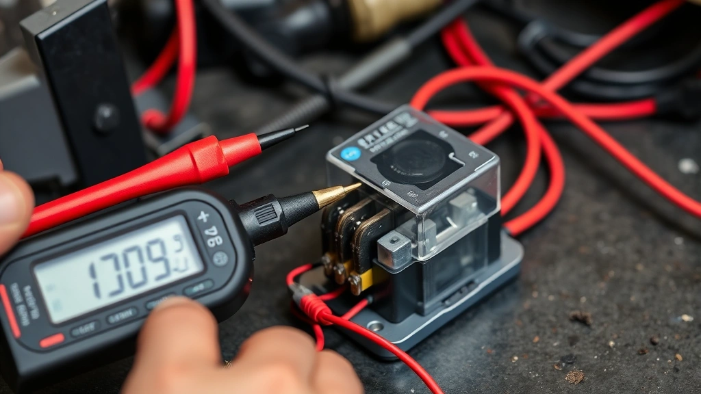
Testing Coil Resistance: Set your multimeter to the resistance (ohms) setting. Connect the probes to the coil terminals (typically 85 and 86). A healthy relay coil typically reads between 50 and 500 ohms, depending on the relay type. Consult your relay’s documentation for the exact specification. If you read zero ohms, the coil is shorted. If you read infinite resistance (displayed as OL or 1), the coil is open and the relay has failed. Make a note of the reading for comparison.
Testing Contact Continuity: Switch your multimeter to continuity mode. With the relay de-energized (no power applied), test the normally-closed contacts. Place probes on terminals 30 and 87a. You should hear a beep indicating continuity. Now test the normally-open contacts (30 and 87). These should show no continuity (no beep). If the results are reversed, the relay contacts are stuck.
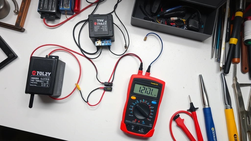
Energizing the Relay: Apply power to the coil terminals using your battery or power supply. Most automotive relays use 12V. You should hear an audible click as the internal electromagnet engages. While energized, retest the contacts. The normally-open contacts (30 and 87) should now show continuity, while the normally-closed contacts should lose continuity. If the contacts don’t switch when power is applied, the relay’s mechanical mechanism has failed.
Resistance Variations: Some multimeters display resistance readings in different ranges. Modern digital meters automatically select the appropriate range, but older analog meters require manual selection. If you’re getting inconsistent readings, try different resistance ranges to ensure accuracy.
This comprehensive multimeter approach identifies most relay failures and provides clear diagnostic information.
The Click Test Method
The click test is a quick diagnostic method that experienced technicians use to verify relay operation without extensive equipment. This method works particularly well for automotive relays and is often the first test performed.
Remove the relay from its socket and hold it near your ear. Using a 12V battery or power supply, apply power directly to the coil terminals. You should hear a distinct clicking sound as the electromagnet engages and the internal switch contacts move. The click indicates that power is reaching the coil and the mechanical switching mechanism is functioning.
Repeat this process several times. A healthy relay produces a consistent, crisp click each time power is applied. If the click is weak, intermittent, or absent, the coil or mechanical components have likely failed. This test is so reliable that many professional technicians consider a responsive click as strong evidence of a functional relay.
However, the click test only confirms that the coil and mechanical switch are working. It doesn’t verify that the contacts are making proper electrical connections or that they can handle the intended current load. For comprehensive diagnosis, combine the click test with multimeter testing.
Advanced Testing Procedures
For complex relay problems or when initial testing results are inconclusive, advanced testing procedures provide deeper diagnostic information. These techniques are used by professional electricians and automotive technicians.
Load Testing: Once you’ve confirmed basic relay function, test whether the relay can handle its rated current load. Create a circuit with the relay controlling a resistive load (such as automotive light bulbs) that draws approximately the relay’s rated current. Observe whether the relay clicks reliably under load and whether the load operates normally. If the relay fails under load but passes basic tests, the contacts are likely worn or corroded and cannot handle high currents.
Thermal Testing: After running the relay under load for several minutes, carefully touch the relay casing (avoiding the coil terminals). A functioning relay remains relatively cool. If the relay becomes hot, internal resistance is excessive, indicating contact degradation or coil problems. Extreme heat suggests imminent failure.
Voltage Drop Testing: Connect your multimeter in series with the relay’s switch contacts while they’re carrying current. Measure the voltage drop across the contacts. A properly functioning relay should have minimal voltage drop (typically under 0.5V). Excessive voltage drop indicates corroded or worn contacts that restrict current flow.
Oscilloscope Testing: For professionals troubleshooting complex electrical systems, an oscilloscope reveals relay behavior in detail. This equipment displays voltage and current patterns, showing exactly how the relay responds to control signals and identifying subtle timing or switching problems.
These advanced methods provide comprehensive diagnostic information but require more specialized equipment and expertise than basic testing.
Common Relay Problems
Understanding common relay failures helps you interpret test results correctly. Different failure modes produce different test results.
Open Coil: This occurs when the coil wire breaks due to vibration, overheating, or manufacturing defects. Multimeter testing shows infinite resistance in the coil, and the relay produces no click when powered. The relay must be replaced.
Shorted Coil: Internal coil insulation fails, creating a short circuit. Multimeter testing shows zero or very low resistance in the coil. The relay draws excessive current and generates heat. Replacement is necessary.
Stuck Contacts: Contacts weld together due to arcing, corrosion, or mechanical failure. The relay produces a click but the contacts remain in one position regardless of coil power. Multimeter testing shows improper contact behavior when the relay is energized and de-energized.
Corroded Contacts: Oxidation on contact surfaces prevents proper electrical connection. The relay may click, but contacts show high resistance or intermittent continuity. This sometimes allows cleaning and repair, but severe corrosion requires replacement.
Mechanical Failure: Springs break or the armature becomes stuck due to rust or debris. The relay produces no click and shows no contact switching. Internal damage requires replacement.
Identifying which failure mode is occurring helps determine whether repair is possible or if replacement is necessary.
When to Replace vs Repair
After testing reveals a problem, you must decide whether repair or replacement is appropriate. This decision depends on the relay type, failure mode, and availability of replacement parts.
When to Replace: Most modern relays are inexpensive and readily available, making replacement the practical choice. If the coil has failed (open or shorted), replacement is your only option. Similarly, if internal mechanical components are damaged, the relay cannot be repaired. Automotive relays typically cost $10-$50, making replacement more economical than attempting repairs.
When to Repair: If contact corrosion is the only problem, careful cleaning with fine sandpaper or specialized contact cleaner might restore function. This approach works best for older relays that are difficult to replace or for industrial applications where relay downtime is costly. However, cleaned contacts may not provide reliable long-term operation, so replacement is usually preferable.
Prevention Measures: Regardless of whether you repair or replace, address the underlying cause of relay failure. Check for excessive current draw, ensure proper heat dissipation around the relay, and verify that the relay is rated for your application. Using a relay with higher current rating than necessary extends its lifespan significantly.
When replacing a relay, ensure the new relay has identical specifications and terminal configuration as the original. Consult your equipment’s manual or the relay manufacturer’s documentation to verify compatibility.
FAQ
How do I know which relay terminals are the coil?
Most relays follow a standard numbering system. Terminals 85 and 86 are the coil connections, while 30, 87, and 87a are the switch contacts. However, always verify using your specific relay’s wiring diagram, as some specialized relays use different numbering. The relay casing often shows terminal numbers, and the documentation provided by the manufacturer clarifies any confusion.
Can a relay work intermittently?
Yes, intermittent relay operation is common and indicates developing problems. Corroded contacts, loose terminal connections, or mechanical wear cause the relay to function sporadically. If testing shows inconsistent results, the relay is degrading and should be replaced soon to prevent equipment failure.
What voltage should I use to test a relay?
Use the voltage specified for your relay’s coil. Most automotive relays operate at 12V, while some industrial relays use 24V, 110V, or higher. Applying incorrect voltage may damage the relay or produce inaccurate test results. Check the relay’s documentation or the equipment manual to confirm the proper voltage.
Is it safe to test a relay while it’s still installed?
Testing a relay in-circuit can be risky because other components in the circuit may be damaged by your testing procedure. Additionally, the circuit’s other components affect your test results. Always remove the relay from its socket before testing, unless you’re specifically diagnosing an in-circuit problem.
How often should relays be tested?
Test relays only when you suspect a problem or when they’re part of critical safety systems. Routine testing isn’t necessary for properly functioning relays. However, if your equipment uses relays that have failed before, consider testing those relays annually or semi-annually as preventive maintenance.
What does a relay click sound like?
A healthy relay produces a distinct, crisp clicking sound—similar to a light switch being flipped. The click happens instantly when power is applied to the coil. A weak, slow, or absent click indicates problems with the coil or mechanical mechanism. With practice, you’ll recognize the characteristic sound of a properly functioning relay.
Can I test a relay with an analog multimeter?
Yes, analog multimeters work for relay testing, though digital meters are more convenient. Set the analog meter to an appropriate resistance range and follow the same testing procedures. Analog meters don’t have continuity beepers, so you’ll need to watch the needle movement instead. Digital meters provide faster and more accurate results.
Related Posts

Superscript in Google Docs: Expert Tips

Strikethrough in Excel: Easy Steps for Beginners
